New York City is one of the most densely populated areas in the world. Containing a population of more than 8.5 million, the city has about 28,000 people/mile2 (10,800 people/km2), a ratio that seems destined to increase. In fact, people keep knocking at the door of the Big Apple to find a place to live and to work; finding all the building space needed to meet this demand is not an easy task.
With buildable land scarce in NYC, the city’s premier real estate developers were in search of a creative solution to maximize the limited space available. Looking out at the bridge industry, they discovered a way to use the high-tech bridge construction machinery to make it happen.
FROM STEELY PLANS TO UNPRECEDENTED PRECAST/POST-TENSIONED SOLUTION
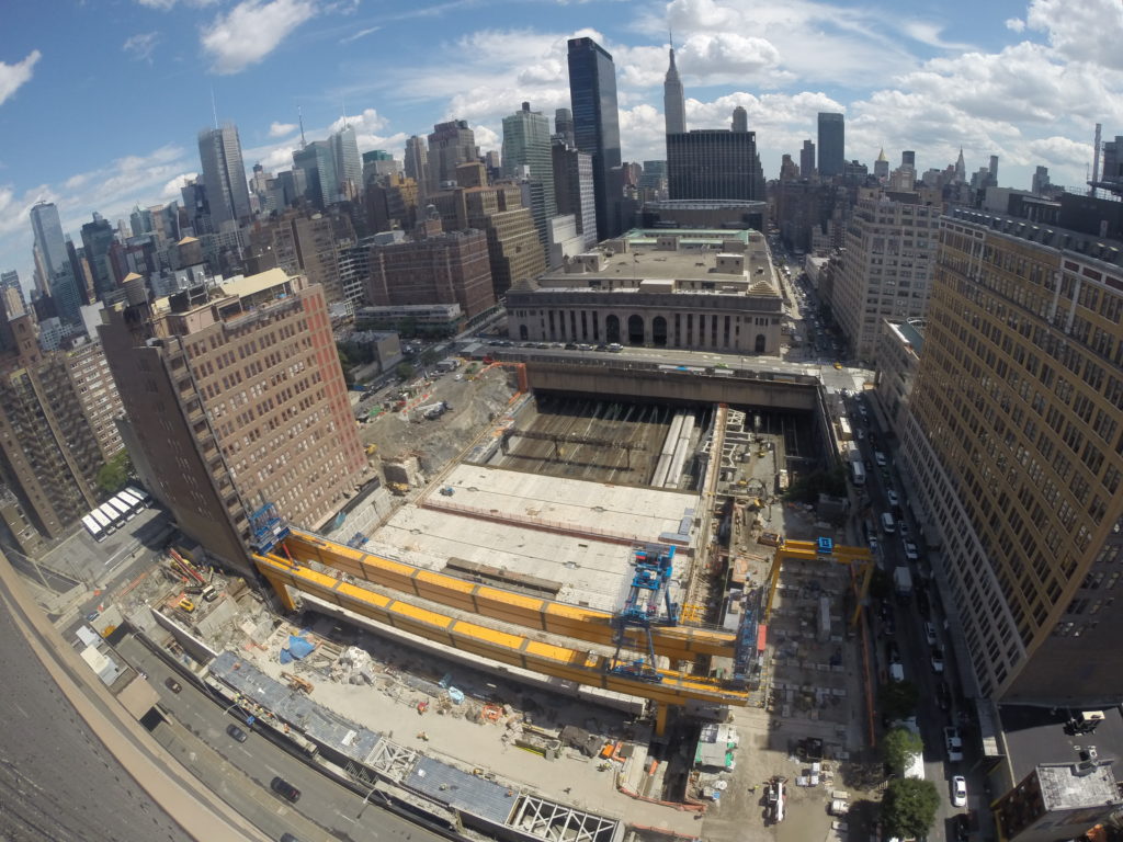
Brookfield Office Properties, owner and developer of the Manhattan West Project, contacted Rizzani de Eccher USA (RdE USA) seeking a solution to close a big gap in the middle of their 7,000,000 ft2 (650,000 m2) development site (Fig. 1) by somehow spanning this air rift with a platform above the high-traffic-volume railway tracks. Brookfield executives had observed the efficiency of the Launching Gantry (LG) RdE USA used to erect precast bridge segments in rebuilding the Roslyn Viaduct in Long Island, NY.
Originally, the platform design called for structural steel. After collaborating with several consultants on an innovative new concept, RdE USA presented the owners with the following alternative solution:
- Use precast segmental post-tensioned bridges to span the entire opening;
- Erect the precast bridge segments with a custom built overhead LG; and
- Eliminate the need to place columns in between the railroad tracks below.
ERECTING MONSTER GIRDER WITH RECORD LENGTH
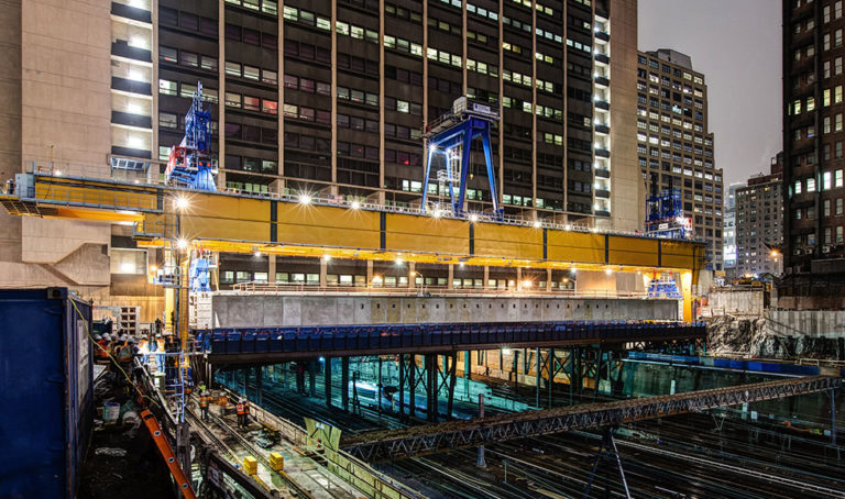
To span the gap, it required an extensive engineering work to come up with a 2400 ton ( 2200 metric ton), precast/post-tensioned 240 ft (73 m) long segmental girders positioned by a custom-built LG above 15 live rail lines and their electrified power lines (Fig. 2). These girders will support a public plaza and parking structure between two highrise buildings.
The girders were placed at a record length of 240 ft (73 m) during the early morning hours 55 ft ( 17 m) above live tracks that run in underground tunnels to Penn Station. Two elements have particularly contributed to the success of the Manhattan West Project:
- The ability of DEAL, a subsidiary of RdE USA, to manufacture a very high-tech piece of LG equipment with the capacity to smoothly place 16 girders in position; and
- The skills of McNary Bergeron to design a precast concrete segmental box girder that could accommodate 100 tons of post-tensioning strands inside. Comprised of 1100 tons ( 1000 metric tons) of steel with a capacity to lift 3600 tons ( 3300 metric tons), the LG has a 90 ton ( 82 metric ton) winch for handling the individual segments before they are epoxied and post-tensioned into a single, giant girder. Every component was designed and manufactured in Italy and broken down into more than 90 containers to allow oceanic transport to NYC.
Before placing the first span, some New Yorkers and other contractors were expecting a dramatic scene: perhaps loud impact noises, or the thrill of precariously swinging loads. But when RdE USA erected the first girder, it was so smooth, silent, and precise that many observers on site were somehow disappointed.
LAUNCHED INFRASTRUCTURE AND SAVING WITH PRECAST
The assembly process is very similar to other sequential span-by-span bridges that use an under-slung LG (Fig. 4). Here, the difference is that a platform is being built, so there is no need for a gantry that launches from pier to pier. Rather, a machine moves sideways to place one completed bridge span adjacent to the next. This is a unique setup in Manhattan and one that could be very useful in any situation where, because of busy train tracks or roadways, urban developers are not able to maximize all the potential real estate space. The most important feature of this type of project is early collaboration during the conceptual phase on construction alternatives that allow placement of columns, slabs, or steel or segmental bridges to maximize design flexibility. In particular, solutions that use precast concrete elements speed up construction and, considering the significant labor rates, keep costs down. Metropolitan Walters played a crucial role in this success. They are a local steel erector with no experience in segmental erection. Nevertheless, the management approach taken by RdE USA has allowed the effective transfer of know-how. Metropolitan Walters has been able to face this challenge with no injuries and completed the work on time and on budget.
The LG solution seems to have been the only economical way to develop these parcels of land. In fact, Brookfield acquired the property in the early 1980s, and it remained undeveloped for decades due to the presence of critical rail traffic.
CONSTRUCTION SEQUENCE
The first activity on-site was the installation of a steel temporary protection platform over the rail lines. It served the dual purpose of protection of the railways and of underslung bed, the “girder factory” from where the LG could be assembled and the girders No. 3 and 4 could be set into place. This temporary protection platform (TPP ) was the only structure that needed column touchdown at the track level. The next operation was the assembly of the LG over the TPP. This procedure was similar to a steel bridge incrementally launched. In this phase, the geometry of the structure was essential. The two main girders were composed of eight elements each with more than 24,000 bolts connecting them. Each module had to be perfectly aligned with the previous to maintain the required line and level.
When all the systems were connected, the precast segment erection operations started. All 39 segments for one girder could be stored in a 6100 ft2 (570 m2) yard on the site. A straddle carrier supplied by DEAL serviced the staging area, offloading the segments that were trucked in at nighttime and placing them in their temporary storage location. The segments had to be double-stacked for maximizing the storage capacity.
To erect the segments, the straddle carrier lifted each segment and brought it to the LG feeding point. At that location, a trolley was bringing the segment from the dropping point of the straddle carrier to the picking point of the LG winch. The winch picked each segment using a C-hook to minimize PT bar tensioning and connection timing. The C-hook lifted the segment beneath its top slab and carried it into place on top of the adjustable screw jacks, over the two steel I-girders that composed the underslung equipment. The segment joints were then epoxied and the first-stage tendons (24 tendons) were connected with temporary PT bars and tensioned on the underslung bed using the launching gantry. After the first-stage tensioning, the camber generated by the PT force was such that 200 tons ( 180 metric tons) of counterweights had to be positioned on top of the deck to counteract the uplift generated by the tensioning of the tendons. The span was subsequently moved to a secondary stage area, where the last 10 PT tendons were tensioned and the final grouting was performed. After the grout had reached the initial set, the counterweights could be removed. The last operations were the installation of miscellaneous material and the punch list correction before the girder placement.
To prepare for the girder erection, the lowering system was connected to the pier segments by means of eight threaded bars. When all the connections were secured, the lifting operations could start.
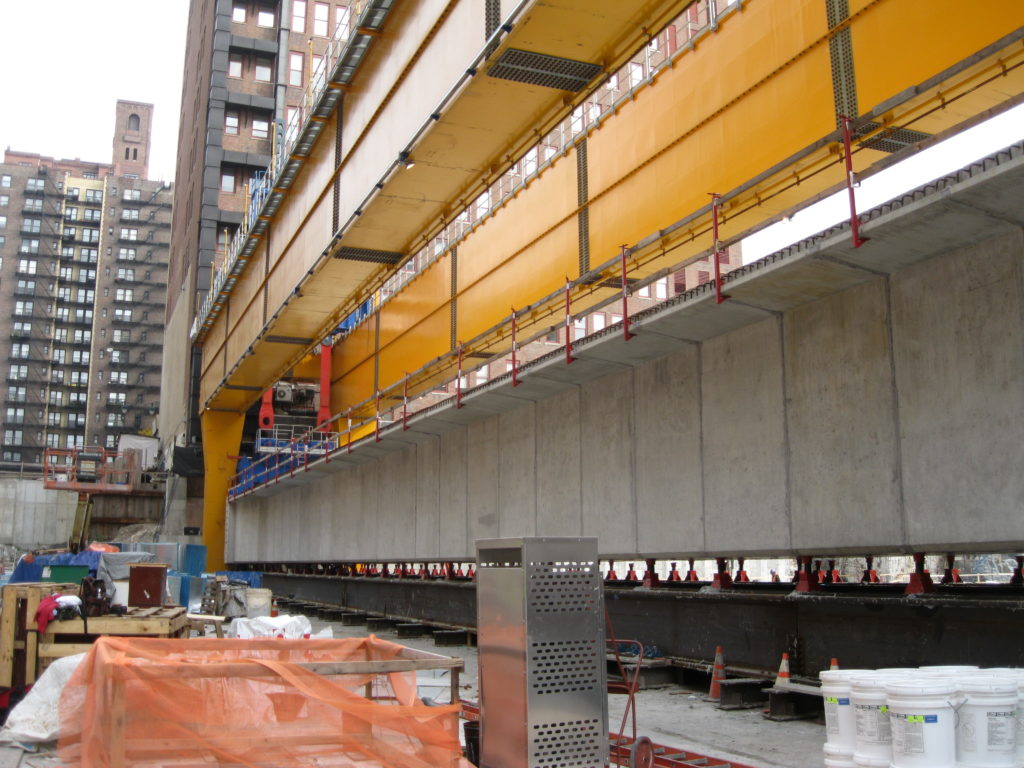
The LG was basically a gantry able to move sideways on rails and its main components were a winch and a lowering system (Fig. 5). The gantry could move 10 ft ( 3 m) per minute and lowered the girders into place at a rate of 0.5 ft per minute with a 1/4 in. (6 mm) precision. The lowering system consisted of hydraulic cylinders with pins and slotted bars (Fig. 5). On each slotted bar, there were two pins that were used alternatively for lifting the girder and for keeping it in position while the jacks restroked. This was a very important feature for the railways’ safety: there was, at all times, a positive connection between the bridge and the erection equipment. Even in case of a hydraulic failure, the load would have always been secured by the pin connection. On top of that, the LG was remotely connected with the engineers and technicians in Italy to monitor the functioning and ensure that all the sensor and indicators were working properly. After the first two girders were set, the TPP was removed and the underslung assembly bed was relocated over Span 3 and 4 and used as the stage from which subsequent girders were fabricated.
Each girder required 100 tons ( 91 metric tons) of post-tensioning supplied by Tensa, using twenty 37-strand and fourteen 31-strand tendons (Fig. 6). The 16 girders created a platform 480 ft (146 m) wide and 12 ft (3.7 m) deep with and a total amount of 612 segments.
The platform was designed as three distinct sections made of seven, six, and three bridges separated by movement joints. The final work, executed by John Civetta and Sons, was placing a 6 in. ( 150 mm) concrete layer on top of the deck and in between the end anchor segments to create a rigid diaphragm across each of the three solid structures (Fig. 7).
As was expected with the magnitude of compressive stress in the structure, small cracks were observed at locations of high stress concentration, such as at the armored openings after post-tensioning. All cracks were relatively small ( <0.01 in. [0.25 mm]) and were sealed with methacrylate crack sealer.
The members of the construction team worked together closely throughout the project to ensure it ran smoothly under challenging conditions in producing a first-of-its-kind structure. Although the structure is not strictly a bridge, the construction of a platform over an active and busy railway addressed many of the same issues that more typical bridge structures encounter, but on a much more massive scale.
COMPLEX GIRDER GEOMETRY
Because of all the geometry control required, precasting segments such as these for the first time was not easy. As a result, RdE USA sent some of its engineers to the precast plant to work side-by-side with Jersey Precast personnel, the precaster that supplied the elements, to ensure an accurate transfer of knowledge for a quality job.
McNary Bergeron designed the precast bridges. Each bridge consists of 37 to 39 match-cast segments individually trucked on site and assembled over the underslung bed.
CONSTRUCTION CHALLENGES
Despite the overall success of the project, there is always room for improvement. For example, the temporary post-tensioning bar configuration was a real challenge because having narrower-than-usual precast segments presented some difficulties in the installation and removal of the rods.
Another significant challenge is the engineering involved in coordinating the design of the bridges and equipment. Because this is such a unique structure, an innovative, seamless approach is required to make it work.
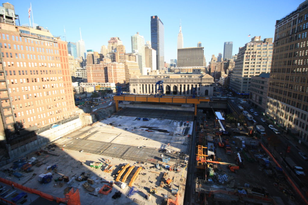
The logistics of the project are also complex, with work taking place on a staging area effectively the size of a postage stamp (250 x 90 ft [76 x 27 m]) in the middle of Manhattan (Fig. 8). Assembling the LG meant trucking in more than 90 very large and heavy containers to a small, confined area where other contractors were also working. RdE USA had significant interaction with SOM ( the project architect) during the design phase. The most critical issues faced were related to creating openings in the platform to possibly allow future columns for the overhead buildings to touch down at the track level (Fig. 9). The platform’s design is very sophisticated and these openings were particularly daunting because of the flow of stresses on the deck.
 NEW URBAN FRONTIER
Beyond the structural challenges and record span lengths achieved, there is one element that lays the foundations for a new way of developing the urban environment. The happy marriage between the structural engineering features of bridge construction and the building industry has paved the way to creating real estate where there seems no opportunity to do so (Fig. 10). The ability to cover an area that effectively was unbuildable suddenly opened up a new possibility of developing apartments, offices, and especially green areas.
The value of this approach is immense in cities such as New York where more and more people are looking for places to live and work. This project has drawn a lot of attention and it appears that many other cities are facing the same problems. In fact, it is evident that many cities have railways, roadways, or other types of active traffic below the street level and close to areas that could potentially be developed.
The top-down construction method that was used in the Manhattan West Project is a technology that could be applied to many other scenarios. Different structural solutions might be implemented, but the application of specialized equipment to ensure a fast and safe execution of the project is a method that allows minimizing the work at the level of the area that needs to be covered.
Location: New York, NY
Owner: Brookfield Properties, Inc.
Architect: SOM
Engineer: ( 1) McNary Bergeron Associates; ( 2) Entuitive Corp.
Contractor: Rizzani de Eccher USA Ltd.
PT Supplier: TEN SA America
Submitted by: Tensa America
Article By, PTI Journal, August 2017